V2.x Floppy drive adaptor (Opensource)
Current Status: Complete
Date: April 2012, updated July 2017
License: Creative Commons Attribution 3.0 Unported License
Introduction
Presented here is a simple circuit that allows PC floppy disk drives to be used with the Amiga and with the V2.5 design,
the Atari ST/TT computers.
This design only supports double density disks. You can fit a high density drive and use it with double
density disks without problems.
The design has been tested using Workbench Format/Copy, Xcopy, Sanity Arte Demo, Spaceballs 9 Fingers Demo,
State of the Art Demo, RSI Megademo and numerous trackloader based games.
Testing on the Atari ST was carried out using TOS 2.06 and Super Stardust to verify correct operation and diskchanges
were correctly detected.
The design also allows you to fit the unit in place of an Escom A1200 floppy drive, which will restore support for
trackloader based games and demos with a simple no solder modification.
Schematics and PCB files are online if you want to make your own unit from Github at https://github.com/istedman/Floppy_adaptor
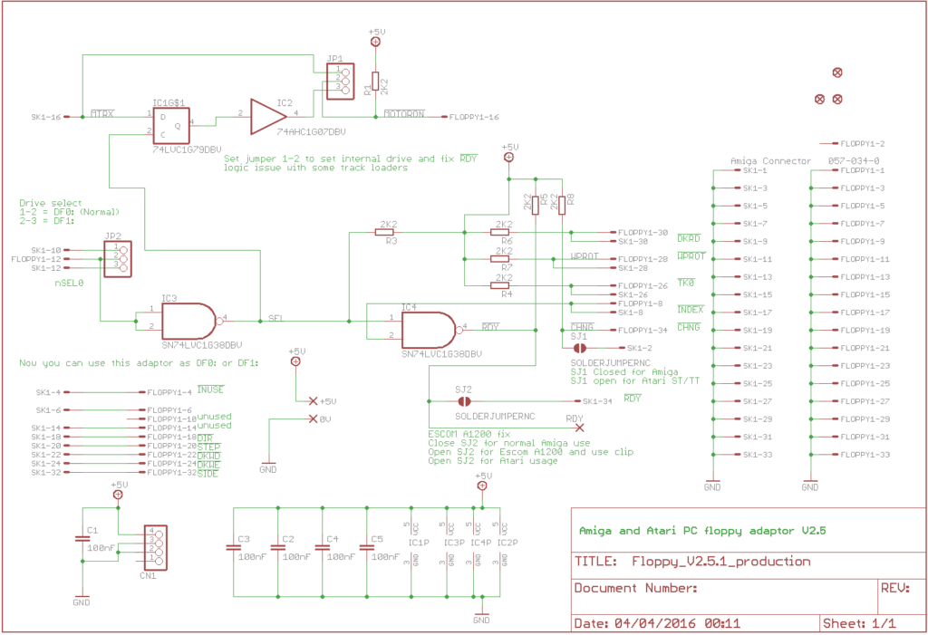
V2.5 Design information
The design is simple, it swaps connects Diskchange from pin 34 of the PC drive to pin 2 of the Amiga. It generates the
nREADY signal based on the nSEL0 signal and nINDEX, which signals to the Amiga that the drive is ready for access.
Swapping DF0:DF1: or A:/B: (Atari) and why it does not work
This section has been added to try and reduce the number of emails I get asking this question.
The updated V2.1 and later designs latched the MTRx signal to allow use as an external floppy disk drive. To use as a driver other than DF0: on the A500/A600/A1200 you must connect it to the 23 pin floppy drive port. On the internal drive connector, only the MOTOR0 drive select signal is available, this will not work with a drive jumpered to DF1:, as was discovered during testing.
If you connect the SEL1 jumper and use the internal 34 way cable, every time drive 0 is connected, the jumpered drive 1 will spin up but not be selected. When the Amiga selects drive 1, it will assert SEL1 but as MTRx is not available, only MTR0 (the motor enable for drive DF0:) the drive motor will not spin up, so you will see DF1:??? on the desktop.
The Amiga has a small D-type, similar to IC1 in my schematic below, on the motherboard, this ensure that when DF0: is SELected, the drive MTRx signal is latched and supplied as MTR0.
To use the adaptor as DF1:, you must connect MTRx and SEL1 from the Amiga 23 way floppy drive connector to pins 16(MTRx) and 12 (SEL) of the floppy drive cable.
To be able to swap DF0: and DF1: or A: and B: on the Atari, would require additional logic. In theory, you could connect SEL1 to MTR1 and SEL0 to MTR0 and this should make the correct drive spin up. You would then need some logic to swap SEL0/SEL1 around based on a switch?
This is easy to do in a small CPLD, tricker in discrete logic. It would not be cost effective to add this to the current design but is planned for a future design revision.
Gotek and HxC floppy emulators only need the SEL0/SEL1 signal as they do not have a motor. You can easily connect one of these as an external drive as they will happily work with SEL1 only, it is when you want to swap to internal operation and have the real floppy, with a motor, that things go wrong. I hope this clarifies the operation of the drives.
Similar rules apply to the Atari ST.
Users of the A1500, A2000, A3000 and A4000 can use the adaptors internally as these systems have
the correct logic onboard but they will need to disable the drive select logic using solder pads, details below.
Design files
The schematic is available here (click to enlarge):
The PCB is shown here (click to enlarge)
The schematic and PCB, in Eagle CAD format are available on github, https://github.com/istedman/Floppy_adaptor
Photo of the assembled PCB

PCB jumper settings
The new V2.5 design has two solder jumpers that allow some configuration of the adapter these settings are summarized in the table below:
| Solder jumper | Amiga | Amiga +Escom fix | Atari |
| SJ1 | Closed | Closed | Open |
| SJ2 | Closed | Open | Open |
It is possible to convert an adapter from Amiga to Atari use or vice versa. If you order a ready assembled PCB, you select the option you want and it comes ready configured.
V2.1 design changes and internal drive selection
As part of the continuous testing and improvements of the design, it was found that the V2 adaptor had a compatibility
issue with the ‘Big Box’ (A1500, A2000, A3000 and A4000) Amigas caused by the drive logic on the motherboard,
acting in parallel with the drive logic on the adaptor thus causing a timing violation when latching the MTRx signal.
It has also been discovered that bypassing the additional drive selection logic fixes a loading issue with some trackloader demos.
To allow the adaptor to function as a drive other than DF0:, with other drive in the system, the onboard logic that latches the MTRx signal needs to be bypassed. An updated V2.1 design has been created that provides solder jumpers to achieve this.
On the V2.1 PCB are two solder jumpers, SJ1 and SJ2.(photo to follow shortly)
| Mode | SJ1 | SJ2 | Notes |
| Normal | Open | Closed | Drive will work internally or externally |
| Bypassed | Closed | Open | Internal use only |
All units ship with SJ1 open and SJ2 closed.
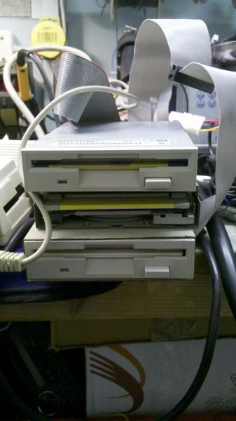
Assembled unit
On the left in this picture is the new V2 adaptor, on the right, is the older V1 adaptor.
Note the orientation and lower profile of the power connector.

Connected to a disk drive

Testing the unit
I have tested the unit with the following un-modified disk drives
Mitsumi FA404M,
Epson SMD300,
Alps DFE354H090F
and Sony TBC
X-Copy (normal, BAMCOPY and NIBBLE copy) all worked fine, I could view the State of the Art
Trackdemo, spent some time testing Speedball 2 (was really crap at playing this at first) and tried a
few different drives. One of my FDDs has died, still have 3 to test with and all worked identically.
Testing the unit as an external drive, here the adaptor has been configured as DF1: and DF2: is my
trusty Amitek external drive.
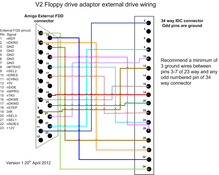
External drive wiring
This picture shows the prototype cable assembly.
NOTE not shown on the diagram below are the +5V and 0V power connections for the floppy drive. You must source this from the Amiga drive port and connect it to your drive. Pin 12 has +5V and pins 3-7 have 0V.
The wiring diagram is presented here,
User manual and installation instructions
The user and installation manual is available to download here, V2_Floppy_adapter_user_manual.pdf (702KB)